5 Plastic Part Design Red Flags (And How to Fix Them)
Comments Off on 5 Plastic Part Design Red Flags (And How to Fix Them)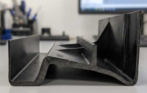
The part design is complete. It looks great on screen. You’re ready to start requesting quotes. You might want to pause before doing so. From experience, we can tell you that the most common production delays or cost overruns don’t happen because of supplier problems. They happen because the design wasn’t properly designed for injection molding.
The good news is that many of these can be worked out before the molten plastic starts flowing. By doing so, you can save weeks of delays, thousands in design or molding costs, and frustration of getting so far, only to go back to square one. In this post, we’ll look at five red flags that we typically see and let you know how to avoid them.
1) Inconsistent Wall Thickness
Designs that have thin walls in one area and thick sections elsewhere, as shown above, are just begging for trouble. This inconsistency leads to uneven cooling, which causes warping, sink marks, and cosmetic defects.
While these problems will quickly surface during first-article trials, they can be avoided completely. To do so, aim for uniform wall thickness. Target thickness should be between 1.5-3mm, depending on the material and functional requirements. For areas that need reinforcement, use ribs rather than thicker walls. These will give you the added strength you need without the cooling problems.
2) Poor Gate Placement
Since the gate is where the plastic enters the mold, flow dynamics should dictate its placement. Otherwise, you run the risk of weld lines, uneven fill, flow marks, and in some cases, weak points in the part. Unfortunately, these issues generally don’t show up early in the run, but in mid-production.
To prevent flow-related problems, gates must be positioned so they allow plastic to fill the mold evenly and completely. Ideally, it should be on a non-critical surface. This way, if any cosmetic marks are present, they are more likely to be hidden. It’s best to work with your injection molding partner to determine where the gates should be placed.
3) Unplanned Undercuts
Some designs will include features such as clips, overhangs, or recessed areas that will create undercuts. Molds typically can’t handle this without complex slides or collapsible cores. These issues aren’t usually discovered until the tooling quote comes back, and it’s much higher than expected. Complexity will always add cost and lead time.
While undercuts may not be completely avoidable for some designs, you do want to identify them early in the process. If your part absolutely requires them, have a discussion with your molder. They are in a great position to tell you if this can be fixed with simple modifications, or if a more complex mold is required.
4) Parting Line on Visible Surfaces
We’ve all seen this at some point. A parting line is created where the mold halves meet, creating aesthetic issues on critical surfaces. Any cosmetic issues discovered in production lead to scrap, rework, or mold modifications.
Parting lines are largely unavoidable. But you can mitigate them by making sure they fall on non-critical or hidden surfaces. If that’s not an option, see if other design tweaks or cosmetic solutions such as texturing can be used.
5) Over-Specified Tolerances
This is one we’ve mentioned before but is definitely worth revisiting. The problem is simply that required tolerances are tighter than necessary (or achievable). Holding over-specified tolerances usually costs more. It also leads to higher scrap rates, frequent adjustments, and production delays.
To avoid over-specified tolerances, work closely with your design team and molder to understand what tolerances are acceptable and achievable for your part’s use, material, and geometry. It’s better to start looser and tighten specs only where functionality absolutely requires it.
Conclusion
While your part design might be functionally perfect, it must do more than look great on your screen. It must be optimized for the manufacturing process as well. Remember that the best time to catch these issues is before the mold gets made. A quick review with an experienced molder can prevent weeks of delays and a significant amount of money. Don’t wait for the first article to surprise you. Design with manufacturability in mind from early on. Your timeline and your budget will thank you!

 Quality – you can’t have a conversation about any type of “job shop” work without mentioning quality. It’s easy for companies to claim they are “all about quality”. But do they have the process and stringent certifications to prove it? With a commitment to quality also comes excellent documentation processes. This helps maintain consistency across future runs. It also supports traceability. If something goes wrong, it will be much easier to get to the source of the problem. For instance, if a part fails due to a material issue, it could be traced back to the supplier and the lot. Don’t just assume a quality program is in place. Ask for certifications. Make sure they can back up their quality commitment claims.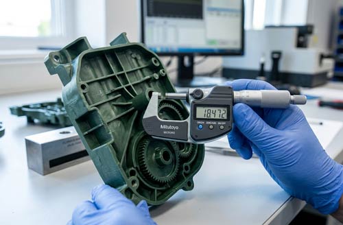
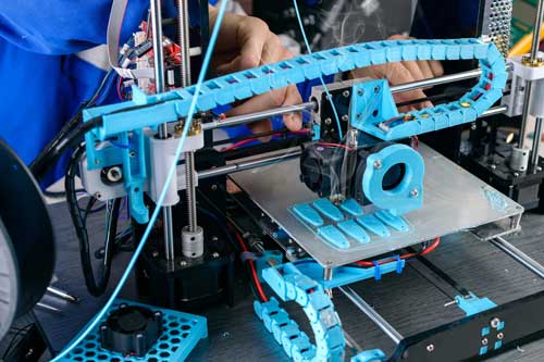 Your prototype is a success. Excellent design, happy customers, and now it’s time to scale. The fun has just begun!
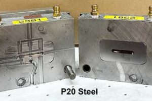 Prototype tooling is perfect for what it’s designed for: short runs and design flexibility. But things like aluminum molds, 3D fixtures, and soft tooling can’t handle the demands of production runs. Imagine if you are starting with 10,000 parts a year, and run 500 cycles per month. If you go to a million parts annually, you’re now at 5,000+ cycles per month. Your aluminum mold will be shot in three months, instead of three years.
 One of the biggest sources of frustration when ramping up is the time it takes to successfully scale from prototype to production. While it can happen quicker, it’s not unusual for it to take up to 24 months to do. Steps such as tooling design, production and testing will likely take several months. Then you’ll need to budget time for tool sampling, iterations, and first article inspection. It takes time to design and produce the molds. Teams that attempt to shortcut this process often sacrifice proper process validation, deal with single-source vulnerabilities, and may end up with expensive design changes.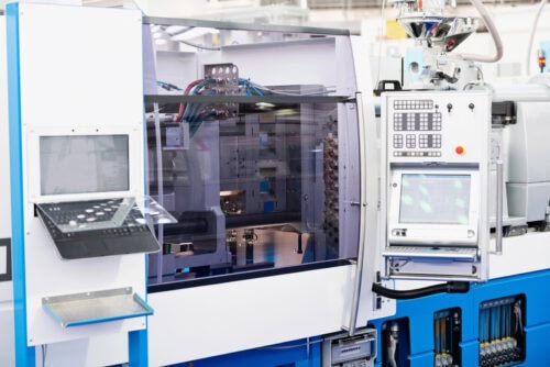
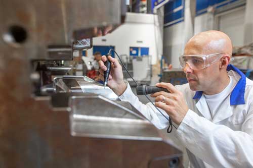 Process validation and documentation – establish processing windows through designed experiments rather than relying on trial-and-error approaches. Document validated parameters thoroughly and implement controls to maintain consistency across different operators and shifts.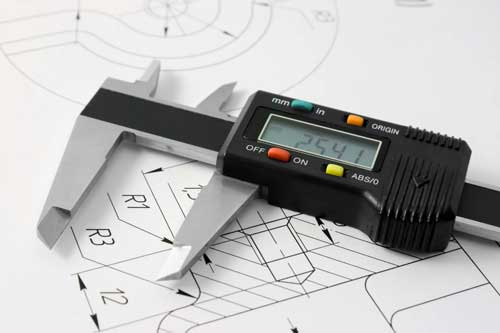
 Application and environmental considerations go hand in hand. The components must be designed to withstand whatever threats they may be up against such as extreme temperatures, force, and chemical or UV exposure. Parts exposed to UV rays will definitely require specialty UV-stabilized materials, while having thicker sections will also help them maintain mechanical properties over time. For industrial applications, chemical resistance is often a critical factor. While food-grade components require specific material selections as well as surface finishes, with the goal of minimizing contamination.
 Design for manufacturability, where parts are optimized against manufacturing complexity, cost and time, extends beyond basic moldability. Key considerations include:
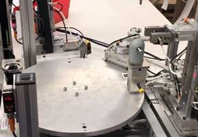 Today’s design for injection molding increasingly incorporates automation to help reduce labor costs and improve part consistency, quality and turn-time. Parts designed for robotic handling also benefit from specific grip features, balanced geometry for stable handling, and consistent orientation features.