Choosing the Right Resin for Your Injection Molded Part
Comments Off on Choosing the Right Resin for Your Injection Molded Part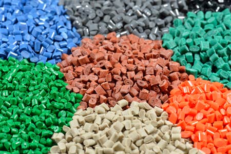
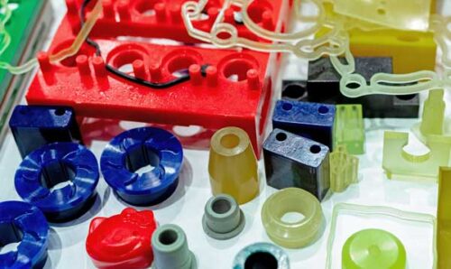
Material selection is a critical factor when injection molding. Selecting the right resign for your injection molded part will be the difference between a product that performs as designed versus one that won’t and could prematurely fail. There are many types of resins available today, each with it’s own set of features, benefits and properties. This guide will help you understand the options and key selection criteria.
Understanding Resin Categories
Molding resins generally fall into two larger categories: commodity resins as follows:
- Commodity Crystalline & Amorphous unfilled and filled with glass, carbon, PTFE
- Engineering and High Performance Crystalline & Amorphous unfilled and filled with glass, carbon, PTFE
Commodity Resins – less expensive, readily available, and perfect for general uses. It is likely that products produced from these materials are within your grasp at this very moment! Commodity resins are further divided categorically into crystalline, amorphous unfilled, and filled amorphous. Let’s examine some examples of each, and what makes them different.
Crystalline Commodity Resins:
- HDPE (High-Density Polyethylene) – excellent chemical resistance and durability
- LDPE (Low-Density Polyethylene) – flexibility and impact resistance
- PP (Polypropylene): – good chemical and fatigue resistance
- PE (Polyethylene) – versatility and moisture resistance
Amorphous Commodity Resins:
- ABS (Acrylonitrile Butadiene Styrene) – good impact strength and aesthetics
- Acrylic (PMMA) – optical clarity and UV resistance
- PS (Polystyrene) – low cost and ease of processing
Engineering and High-Performance Resins
When compared to commodity resins, these materials offer superior mechanical properties, temperature resistance, and chemical resistance. They tradeoff is a higher price tag, but required for more challenging operational environments. They too are further categorized into crystalline and amorphous groups. Here are the most popular ones, and their defining features:
Crystalline Engineering Resins:
- Acetal (POM): – excellent dimensional stability and fatigue resistance
- Nylon (PA) – outstanding strength and wear resistance
- PBT (Polybutylene Terephthalate) – food electrical properties with chemical resistance
- PET (Polyethylene Terephthalate) – superior wear resistance and dimensional stability
- PEEK (Polyether Ether Ketone) – exceptional temperature resistance and strength
- PPS (Polyphenylene Sulfide) – excellent chemical resistance and dimensional stability
Amorphous Engineering Resins:
- Polycarbonate (PC) – high impact strength and optical clarity
- Urethane – outstanding abrasion resistance and flexibility
- PSU (Polysulfone) – high temperature resistance and hydrolytic stability
- PEI (Polyetherimide) – excellent flame resistance and dimensional stability
Filled vs. Unfilled
The standard properties for commodity and engineering resins can be further enhanced when supplemented by various fillers such as:
- Glass Fiber – improves strength, stiffness, and dimensional stability
- Carbon Fiber – provides excellent strength-to-weight ratio and electrical conductivity
- PTFE (Polytetrafluoroethylene) – reduces friction and improves wear resistance
Key Selection Factors
Determining which material is best for your specific part relies on making sure you understand several key considerations:
Application Requirements – operating temperature range, chemical exposure, mechanical load conditions, lifespan, and regulatory compliance considerations
Mechanical Properties – tensile strength, modulus, and resistance factors for impact, fatigue creep, and wear
Environmental Factors – moisture and UV exposure, chemical contact, and temperature fluctuations
Processing Considerations – mold shrinkage rates, flow characteristics, frying requirements, cycle time implications, and post-molding operations
Economic Factors – cost of raw material, processing efficiency, part consistency, expected service life, and total cost of ownership
Making Your Selection
Choosing the right resin ultimately becomes a tug-of-war between performance requirements and cost. For simpler, cost-sensitive applications, PP, PE, or ABS might be just right. Household items, packaging, and toys often use these resins. For mor moderate performance, enhanced commodity resins (with glass or other fillers) or basic engineering resins like nylon or acetal would be a better option. These are suitable for automotive components, consumer electronics housings, and appliance parts. For more demanding applications, high-performance resins like PEEK, PPS, or PEI must be used to resist extreme temperatures, corrosive chemicals, or heavy mechanical stresses. Medical devices, aerospace components, and automotive components often require these high-end materials.
If in doubt, your injection molding specialists or material suppliers can provide guidance based on what you must accomplish in the application. The choice is ultimately yours to make at the direction of your design engineering team, but specialists can at least help narrow down your options.
 The changing conditions in the global marketplace have manufacturers reconsidering just about everything, particularly their supply chains. Whie this environment can be challenging, the goal remains simple: to continue to maximize profit and efficiency, while minimizing risk. Tariffs in particular have placed urgency on these considerations. But the case for reshoring your plastic injection molded parts goes beyond uncertain economic policies. Today, we’ll lay out a plan for your plastic part sourcing, regardless of tariff outcomes.
 Bringing Injection Molding Home
 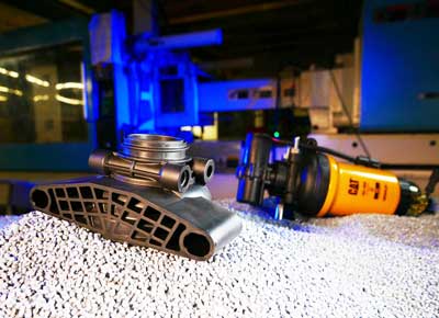 Today, manufacturers are constantly looking for effective ways to reduce costs while improving product performance and production efficiency. One way to achieve this is by shifting from traditional metal parts to thermoplastic ones.
 Along with the advantages listed above, there are some potential drawbacks that must be considered. Selecting the material that meets the performance requirements of the application is crucial – since thermoplastics vary in their properties and performance characteristics.
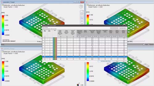
 Post-Processing and Assembly – some parts may require post-processing or assembly steps. These include finishing, such as painting, coating, or surface-treating to achieve the desired appearance or performance.


 Molded thermoplastics may be worked using a few different methods: injection molding, blow molding, and extrusion. Injection molding involves heating plastic pellets to a molten state, injecting it into a mold cavity under high pressure, then allowing it to cool and solidify.
 Thermosetting plastics, simply known as thermosets, are polymers that undergo a chemical change when heated, thus forming a rigid structure. Once set, they cannot be remelted or reshaped. When compared to thermoplastics, they are usually more stable, but also more brittle. Typical materials include Epoxy, Phenolic, Melamine, Urea-formaldehyde, and Polyester resins.
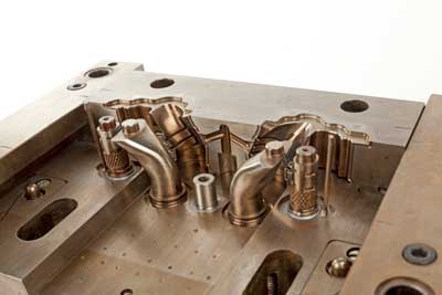 This process involves shaping rubber materials, which can be either natural or synthetic rubber (elastomers). Rubber has high elasticity and abrasion resistance with good tensile strength. These properties vary based on the type used, which include Natural Rubber, Neoprene, and Nitrile Rubber.
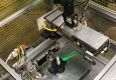
 will utilize inline part inspection to help ensure part quality. With this critical step, an image of the finished part is taken, compared to a reference image, and is either accepted, or, sadly, pushed into the reject bin. (But don’t be too sad, that part will get a second chance here at PDI, since we recycle all excess plastic inline!)


