Design for Injection Molding
Comments Off on Design for Injection MoldingEssential Guidelines for Injection Molded Part Design & Manufacturing
Design for injection molding is much more than just part design, it is a comprehensive process that must consider all aspects of the plastic component and the manufacturing process. These considerations primarily include part geometry, material selection, processing, tooling, quality and, of course, the financial aspects. Ultimately, the goal is to produce parts that can be made reliably, efficiently, and cost-effectively at the needed production volumes.
Proper design for injection molding also requires a solid understanding of the technical aspects of how part design decisions interact with manufacturing variables. For example, how do the material properties affect flow and cooling? How does the geometry of the part influence mold complexity and cycle time? How do end-use environmental considerations drive material and design choices? And how does production volume and component complexity impact tooling and automation choices.
Key Technical Injection Molding Part Design Considerations
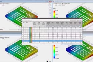
Effective injection molding part design starts with a good understanding of how molten plastic flows, cools, and then solidifies within a mold cavity. Key considerations and features include:
- Wall thickness consistency is perhaps the most critical factor. The goal is to have uniform wall thickness, which helps ensure even cooling. This prevents part defects like warping, sink marks, and internal stresses. When you get this right, you will benefit from reduced scrap rates, more efficient material use, and a healthier bottom line.
- Draft angles, which represent the slight taper on vertical surfaces that are in the direction of the mold opening, are equally important. The Ideal target is 1-3 degrees, which is needed to facilitate smooth and reliable part ejection from the mold. Without proper draft present, parts are much more likely to stick in the mold, or suffer surface damage during ejection. Sharp edges should also be avoided wherever possible, as stress concentrations around sharp corners can also lead to part failure and complicate the overall molding process.
- Ribs, or thin reinforcing walls, will add structural strength without excess material consumption. They should generally be 40-80% of the nominal wall thickness to provide benefit, while avoiding sink marks on opposite surfaces.
Functional Considerations
Every injection molding part design must also take careful consideration of the functional requirements of the component or assembly. These include, but are certainly not limited to: the application, material selection, and environmental factors. These interdependent variables must be considered at the holistic level in order to achieve the best part performance and manufacturing efficiency. Let’s take a look at each of these:
 Application and environmental considerations go hand in hand. The components must be designed to withstand whatever threats they may be up against such as extreme temperatures, force, and chemical or UV exposure. Parts exposed to UV rays will definitely require specialty UV-stabilized materials, while having thicker sections will also help them maintain mechanical properties over time. For industrial applications, chemical resistance is often a critical factor. While food-grade components require specific material selections as well as surface finishes, with the goal of minimizing contamination.
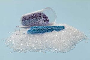
Keep in mind that material selection will also directly impact the feasibility of your injection molded part design. Let’s look at a few examples. Glass-filled nylon offers excellent strength but requires larger corner radii and may cause fiber orientation effects. TPE materials provide extra flexibility but also need different gate locations and runner designs when compared to rigid thermoplastics. Each material group brings unique flow characteristics, shrinkage rates, and processing requirements that must inform design decisions.
Design for Manufacturability (DFM)
 Design for manufacturability, where parts are optimized against manufacturing complexity, cost and time, extends beyond basic moldability. Key considerations include:
- Gate placement – which significantly affects both part quality and cycle time. Ideally, gates should be in thick sections to promote proper filling while minimizing visible marks on exposed part surfaces.
- Undercuts – should be minimized or eliminated when possible, since they require costly side-actions or complex mold mechanisms. When undercuts can’t be avoided, designing them for simple cam-action mechanisms will help reduce tooling costs when compared to hydraulic cylinders or complex slides.
- Parting line placement also affects both part appearance and mold complexity. Strategic parting line positioning can eliminate secondary operations while maintaining aesthetic requirements. Consider how flash removal, if necessary, will be accomplished during production planning.
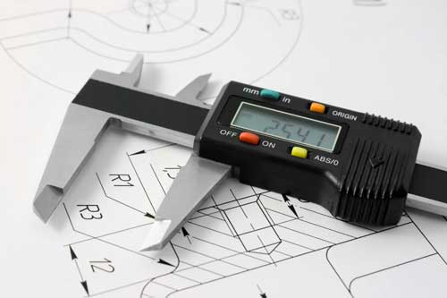
Tolerance Considerations
As we previously discussed, tolerances are yet another key consideration. Under-specifying this could lead to part or system failure, while over-specifying increases production costs and may also require secondary operations. Keep in mind that injection molding typically achieves tolerances of ±0.003-0.005 inches (±0.08-0.13mm) on most dimensions. Tighter tolerances are possible with careful design and processing control for more demanding applications.
Key factors that affect tolerances include direction of draw and material shrinkage. Direction of draw dimensions, the ones parallel to the mold opening direction, generally hold tighter tolerances than cross-parting line dimensions. Features that are molded with the same cavity half will typically maintain better relative positioning than features spanning the parting line.
Material shrinkage varies both between different plastics and within the same part due to flow patterns and cooling rates. Semi-crystalline materials such as nylon exhibit higher shrinkage than amorphous materials like ABS, and require different tolerance strategies in your injection molding part design.
Integrating Automation for Efficiency and Cost Reduction
 Today’s design for injection molding increasingly incorporates automation to help reduce labor costs and improve part consistency, quality and turn-time. Parts designed for robotic handling also benefit from specific grip features, balanced geometry for stable handling, and consistent orientation features.
Insert molding can also eliminate assembly operations by incorporating metal components during the molding process. However, insert placement, retention features, and thermal expansion compatibility require careful engineering to prevent molding defects.
Design for Injection Molding Success
Successful design for injection molding requires balancing multiple competing factors: functionality, aesthetics, manufacturability, and cost. Early collaboration between design teams and experienced molding professionals will help ensure that injection molding part design decisions support both product performance and manufacturing efficiency.
By implementing these principles from the initial concept phase, you’ll avoid costly design revisions, reduce time-to-market, and achieve optimal part quality in production. Our final thought: always keep in mind that small design modifications early on can result in significant improvements in manufacturability and help keep long-term production costs in check.